Lecture 6
Position sensitive detectors
Even though a CCD may sound like the ideal detector,
real devices suffer from a lot of problems. Some of them are intrinsic
properties of the chip and can not be avoided. Other problems come from
less than perfect electronics or environmental effects. I will go
through a range of topics related to CCD's using a set of
transparencies.
-
Bad columns, hot pixels, dead
spots. These are defects of the chip.
-
Readout noise. This is a noise, which come partly from
the chip but also from other sources. Amplifiers need to be tuned
carefully and ground connections must be properly done.
-
Fringing. Thin chips can suffer from interference
patterns, mostly in the red part of the spectrum. Especially in
spectroscopy, it is a difficult issue to handle.
-
Frontside/Backside illumination. Thin chips have been created to reach up
to 90% quantum efficiencies. It is a costly process leading to very
high prices for good devices.
-
Dark Current. Thermal electrons are
released in the chip. At room temepratures the rate is very high. In
astronomy CCD's need to be cooled to temperatures close to -100C. At
these temperatures the dark current become negligible. Negligible means
below the readout noise.
-
Dust and sensitivity variations. Due to the variation in the silicon, all
pixels in the CCD do not have the same detection rate of photons. Dust
will accumulate on the optics in front of the detector and cause
shadows. These effects need to be corrected with a flatfielding
procedure.
-
Bias determination. The voltage measured contains an offset:
the bias. This is often done by using an overscan region, which is an
addition to the image, where no charges are shifted out, but the level
measured repeatedly corresponding to no charge.
-
Gain determination. The Analog to Digital Converter (ADC)
will generate a 16 bit number. Each bit or unit in this number
corresponds to a number of photoelectrons. In order to calculate the
noise levels to be expected (photon noise, readout noise), the gain
(electrons/ADU) needs to be measured
-
Binning. It is possible to combine charges from
different pixels. 2x2 pixels can be combined to reduce the effect of
the readout noise, or to speed up the readout.
-
Scattered light. Scattered light in the telescope or other
part of the optical system can falsify the background and lead to
flatfielding errors as well as errors in the determination of sky
levels. Moonlight can be refelcted into the camera and create strange
shadows and reflections.
-
Guiding. If the telescope do not track well,
images will move on the CCD. This can lead to bad PSF functions, or it
leads to shifts between images and changes in the measured magnitudes
due to the problems connected with precise flatfielding of CCD's.
This is not a complete set of topics that one must care
about, if high precision measurements are required. But it underlines
the need to avoid using instruments as black boxes.
Bias and flat fields
The following images are from observations at the IAC 80
telescope at the observatory on Tenerife obtained during observations
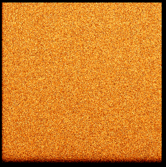
by students in 2005. The first image is a zero image, which is what you
get when you subtract the bias value from several exposures without
opening the shutter (t=0) and take the mean.
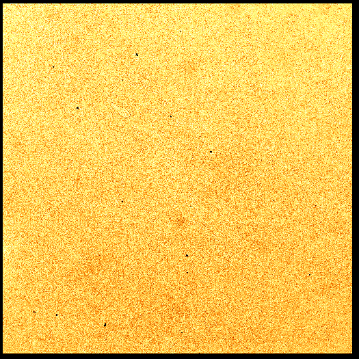
Next an example of combining several exposures of the
sky is shown, where first you subtract the bias value and then the zero
image. Then a median image is created, which is the one shown here for
a B filter. The flat field for this instrument is unusually 'flat'.
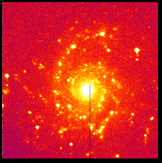
Finally an image of the galaxy M74 is presented, where
now an Hα filter has been used. The effect of using the
Hα filter is that many starforming gasclouds stand out, which
shows that star formation take place in the spiral arms.