Article presented by Karl Ove Nielsen at: Conference on Applications of Ion Beams to Semiconductor Technology, Grenoble, May 1967
The background for this contribution is the experiences we have acquired in a three-year period of ion implantation at the Institute of Physics, University of Aarhus. The accelerators, which have been used for implantation were not originally constructed for this purpose. Their main purpose was the study of collisions of atomic particles in the energy range up to the MeV region. As such a programme also includes the study of penetration of all types of atomic particles in matter, the possibility of ion implantation lay near at hand. Therefore, shortly after the research programme around the Aarhus accelerators started in 1964, contacts with the semiconductor laboratory at the Technical University of Denmark were established in order to also utilize the accelerators for ion implantation of semiconductors.
From an accelerator point of view, ion implantation of semiconductors is a special case of the more general subject of introduction of atoms in matter by means of ion injection. The development of this method goes back to the thirties when it was used in target preparation at some of the very first nuclear reaction studies with accelerated ions. During the last fifteen to twenty years, the method has been employed to a great extent for the collection of microgram or smaller quantities. The value for nuclear spectroscopy of radioactive sources prepared by ion implantation cannot be appreciated enough. The last five to ten years have also shown the significance of the ion beam technique to solid state physics in general.
Accelerators may be used in semiconductor research within the following fields:
Only accelerator problems in connection with these points will be discussed, and here there is no doubt that the largest difficulties will be met in connection with ion implantation. Although location of impurities and radiation damage studies in semiconductors by means of accelerator techniques require an extremely advanced technique, the demands on the accelerator are normally only a well stabilized proton beam with comparatively low energy. A short survey of the special demands on the accelerator for ion implantation will be given and a universal ion source for this purpose will be described. Finally, a description will be given of the two Aarhus accelerators which have been used for ion implantation.
On Fig. 1 is shown the range of atomic particles in a random direction in silicon and germanium1). The lowest energy necessary for ion implantation is decided by the fact that it must be possible for the atomic particles to penetrate the amorphous or disordered surface layers. If, arbitrarily, this surface layer is assumed to consist of approx. 10 atomic layers, i.e. 30-40 Å or 1-2 µg/cm2, the lower energy limit for heavy particles is 10-20 keV. For light particles, the range is higher, but a lower energy limit of 10-20 keV seems reasonable also in this case.
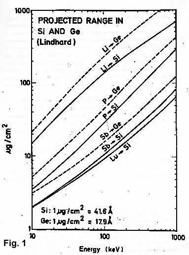 It is not possible to specify the highest energy necessary. From Fig. 1 it appears that an energy range up to 1 MeV gives implantation depths sufficient for most proposed applications.
Also the possibility of utilizing channeled particles for implantation should be considered. Such particles penetrate 6 to 8 times deeper into crystals than particles in random directions do. Recent measuremente2,3) of the distribution of channeled potassium and xenon in tungsten crystal show that at a very precise alignment, two separated peaks in the distribution appear, corresponding to channeled and non-channeled particles. Similar precise investigations of the distribution of impurity ions in silicon and germanium have not yet been completed. Difficulties in the utilization of the channeling effect for ion implantation may, however, be expected since a reproducible distribution demands an extremely well-defined beam and a precise alignment of the crystal.
For most implantation studies, a high energy stability is not required. However, the control of the impurity profile by appropriate choice of particle energy and concentration is very important. The energy, therefore, should be regulated and stabilized with sufficient precision so that variation in range distribution from energy variation should be an order of magnitude smaller than the range straggling. This demands an energy stability of about 1%.
There are, however, other reasons for requiring a considerably better energy stability. For impurity location4,5) and radiation damage studies6), a proton beam with an energy stability better than 0.1% is required.
At the relatively small current intensities used here, it is not so imperative to utilize the electrons deriving from the ionization of rest gas for space charge compensation. This fact makes it possible to use a complicated lens system along the beam because the "drain" of electrons caused by this may be tolerated. A complicated lens system makes it possible to obtain flexibility of beam shape and position, and the beam may be tailored to the specific requirements. This 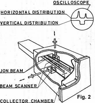 means that the size of the beam at the target may be altered from a few mm2 to ~ 1 cm2. If larger areas are needed, this may be achieved by sweeping the beam. Alternatively, the target may be moved periodically during implantation. As uniformity of the implantation may be significant, the wave-form of the sweeping voltage should be carefully chosen.
A continuous supervision of the shape and position of the beam at various places in the accelerator is important. It is particularly important to measure the beam current distribution at the collector in order to control the uniformity of the deposition of impurities. The current distribution and the position of the beam may be measured by means of a vibrating beam scanner7), see Fig. 2.
If the channeling effect is to be exploited, a beam with an angular divergence of the order < 0.2º is often required. In such cases, the beam direction may be defined by 1 mm slits placed at intervals of several meters. Drastic reductions of intensity might, however, be the result of such an arrangement8).
The number of elements which it might be of interest to implant as impurities in semiconductors is so large that in actual practice an accelerator, which can handle more or less all - or even all - kinds of ions in the periodic system will be desireable. Here, the ion source determines the range which the accelerator will be able to cover.
In section 2, the ion source will be described in more detail, and it will appear that it is possible to cover more or less all elements in the periodic system with reasonable efficiency.
It is desirable that the accelerator be able to handle a beam consisting of radioactive isotopes. For many investigations, the application of tracer technique is necessary, often as a consequence of the fact that the quantity of implanted material should be extremely small if radiation damage be avoided. Certain demands on the accelerator, and in particular on the ion source, must be satisfied before a radioactive beam can be obtained. Precautions should be taken to keep down radioactive contamination.
With the specific activities available at present, the current intensity necessary for the acceleration of radioactive isotopes is usually less than 100 µA. Here, an accelerator with a flexible lens system for moderate current intensities is particularly well-suited. The accelerator should be equipped with a magnet with resolving power large enough for isotope separation in order to make it possible to work with the extremely weak beam of radioactive isotopes and still avoid the beam of stable isotopes. A focusing system like that makes it possible also to adapt the dimensions of the beam according to requirement. In this way it can be avoided to irradiate with radioactive isotopes a larger target area than necessary.
In many cases, isotopic separation of the beam is not required. But in those cases where radioactive isotopes are implanted, small fractions of the stable current from neighboring isotopes may be larger than the radioactive beam current. The demand for separation power may 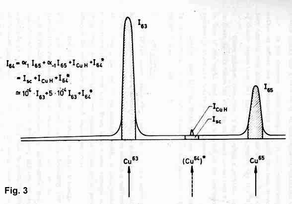 therefore be quite large. Figure 3 shows an example from an experiment recently performed at the Institute of Physics, University of Aarhus9). Radioactive Cu64 was produced by neutron capture in a reactor, so the ratio Cu64/Cu63 in the ion source was limited by the reactor neutron flux. At the position of mass number 64, the following currents were obtained:
1) I64 = beam current of radioactive Cu64. In the actual case, I64 ~ 10-5 I63.
2) Isc = ?1 I63 + ?-1 I65 = current of scattered stable Cu atoms for neighboring isotopes with mass number 63 and 65. In the actual case, Isc ~ 10-4 I63
3) ICuH = current consisting of molecular (Cu63H)+. In the actual case, ICuH ~ 5*10-4 I63 *)
*) Here, it is supposed that this stable beam consists of (Cu63H)+. Still, there is a possibility that it might consist of other molecular compounds with mass number 64.
The current of stable Cu atoms at the position of Cu64 is still an order of magnitude larger than the current of radioactive Cu64, although some improvement has been obtained. This large current of stable copper may give rise to an unacceptable radiation damage. In the above-mentioned examples, it is a relatively simple matter to reduce the contribution of stable Cu atoms since we are here dealing with atoms with mass numbers different from Cu64 by means of double separation. But this will not remove the (Cu63H)+ ions. Since hydride formation is very often a problem, special attention is given to this case. As will be mentioned in section 2, much could be done if the right conditions be created in the ion source, but apparently there are limits to this approach. Another possibility, which is being investigated at present, is to decompose the molecular compound by stripping in a gas immediately before the analyzing magnet.
If the upper limits for irradiated area and depth are specified to 10 cm2 and 10,000 Å, respectively, a dose of approx. 1011 atoms (or 2,000 µA sec) is required in silicon to obtain a uniform concentration of 0.5 atomic per cent to the maximum depth. In this connection, such a concentration is very high. Thus, with a beam current of a few uA, it is possible, even with very reasonable irradiation periods, to achieve the necessary number of implanted ions.
The accelerator should, however, be able to handle a considerably larger beam current than that directly necessary for the implantation. For instance, when radioactive isotopes are implanted, large currents of stable isotopes may be unavoidable because of specific activity limitations. Furthermore, the use of chemical compounds as source material may give rise to considerable currents of foreign particles in addition to the useful beam current. Experience shows that a total beam current of a few hundred µA seems reasonable.
Efficiency usually plays an inferior part in accelerators; it is, however, very important for the acceleration of radioactive ions. High efficiency is required to avoid radioactive contamination of the accelerator. An efficiency of 3% is desireable. Since the transmission through the ion-optical lens system and the deflection magnet is nearly 100 %, the decisive factor is the efficiency of the ion source.
Even though many ion implantations may be performed at a pressure of the order of magnitude 10-6 mmHg, a considerably lower pressure will be required in many cases. The greatest concern is the avoidance of oxide film growth and carbon deposition on the surface of the target. In this direction, much may be gained by using well-constructed cooling traps, although in many cases, metal packings and ion pumps will be necessary.
It is important that the collector chamber be large and that it be possible to use it with auxiliary equipment. Two arrangements, which we have found to be especially important, are:
1) A magnet with high energy-resolution for studies where the energy resolving power of solid state detectors Was insufficient. In several cases, a proton energy resolution corresponding to a depth resolution of ?R ~ 50 Å is required4-6). Here, an analyzing magnet10) with an energy resolving power of 0.02 % is necessary.
2) Equipment for the precise crystal alignment. Many implantation studies call for a precise orientation of the crystal. By using the Rutherford scattering technique11,12), it is possible from the location of sharp planar dips to orient a crystal relative to the axis of rotation with an accuracy of 0.02°. Since it is important that this orientation be performed in the collector chamber with the same slit system for collimation as that used at the subsequent ion implantation, the ion source arrangement should be such as to allow an easy switch-over to a proton beam.
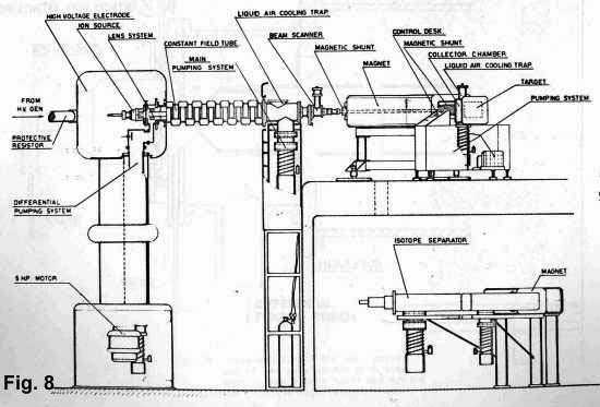
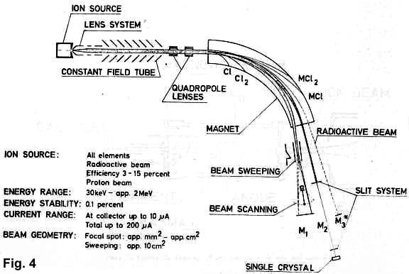 Figure 4 shows schematically an accelerator for ion implantation where the most important of the formerly mentioned requirements have been met. Some typical target arrangements have been roughly shown.
As previously mentioned, the ion source is the most decisive factor of the accelerator in connection with ion implantation. Naturally, several types of sources may be used. In principle, the type which is used in Aarhus at present, was developed at the Niels Bohr Institute during the fifties13,14). During the last few years, the Niels Bohr Institute and the Institute of Physics at Aarhus between them have endeavoured to further develop this type of ion source, and it is the latest version of the source which is described here*).
*) The newest version of the ion source now in use is the result of work done by a team consisting of G. Sidenius and O. Skilbreid, the Niels Bohr Institute, and H.E. Jørgensen and Vagn Toft, Institute of Physics.
The two accelerators at Aarhus are equipped with more or less identical ion sources. This has the advantages that operating experience from one accelerator may be used on the other and that the spare parts stock may be shared.
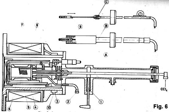
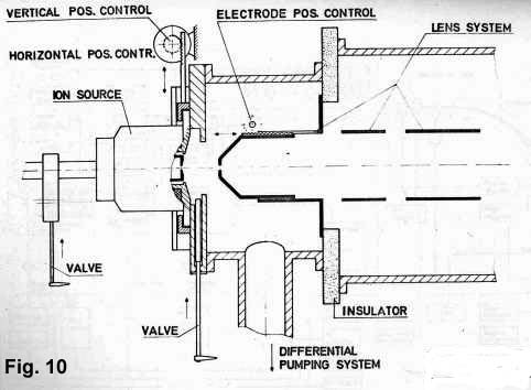
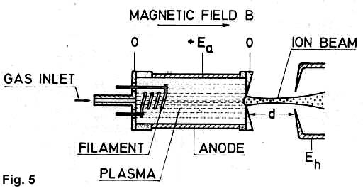 The ion source is of the magnetic type with oscillating electrons (see Fig. 5). At a pressure in the discharge chamber above a certain minimum pressure, a plasma with a high ion concentration is formed and ion extraction takes place in the same direction as the magnetic field (end extraction). The latest version of the ion source is shown in Fig. 6. It mainly consists of three parts: (i) outer house with magnet coil winding, cooling mantel, and valve, (ii) discharge chamber with heat radiation shields, and (iii) sublimation furnace.
The temperature of the discharge chamber must be high enough. to avoid loss by condensation. At such conditions, the pressure in the discharge chamber is determined by the temperature of the sublimation furnace and therefore temperature regulation of this is very important. Normally, the temperature of the furnace is lower than that of the discharge chamber. The construction now in use allows a temperature up to about 1100 °C. With the materials used to-day, it should be possible, with a few modifications, to reach temperatures very near 2000 °C.
 To some extent, the discharge chamber must be vapour-tight so that the escape of neutral molecules and atoms is confined to the outlet.
The feeding of charge material into the discharge chamber may be performed in one of the following four ways:
1) For gases and gaseous compounds, the feeding takes place through a remote-controlled needle valve.
2) For materials which give a reasonable vapour pressure (10-2 - 10-3 mmHg) at temperatures below 1100°C, the pure element may be used as charge material. In that case, two furnaces may be used, one with a separate heating system (Fig. 6B), and one where the heat from the discharge chamber is used for heating the furnace (Fig. 6C) . In the latter case, the temperature is adjusted by regulating the position of the furnace15). This kind of temperature control is faster than temperature control by means of an electrically heated furnace with a separate heating system as shown in Fig. 6B.
3) For materials which are difficult to evaporate, it is necessary to use more volatile chemical compounds as charge material.
4) The CCl4-method, which has been developed especially for microgramme quantities, of rare earths16), may also be used for other materials. The conversion of materials, which are very difficult to evaporate, into more volatile chloride compounds takes place inside the ion source immediately before the entrance to the discharge chamber. The CCl4-flow is controlled by a needle valve.
If it is at all possible, it is an advantage to use the pure material as charge material. In this way, the accelerator is not loaded with a beam consisting of  foreign atoms and molecules. Further, the risk of contamination or destruction of the target (because of bombardment with molecular ions of the same mass number as those to be collected) will be smaller here than if chemical compounds were used as charge material.
The construction material for the discharge chamber and the sublimation furnace should be carefully chosen. For electrodes, graphite and stainless steel are almost exclusively used while insulators are usually made from quartz or boron nitride. Here, it should be emphasized that high temperature together with CCl4 or similar compounds make rather heavy demands on the construction material for the discharge chamber. The following points should be considered: (i) High temperatures and Cl-compounds require graphite or quartz. (ii) For gases and many pure elements, stainless steel may be used. For materials, which form carbides, graphite should in no circumstances be used. (iii) Boron nitride has many advantages as insulating material, and it has been used for copper and other elements with good results. But we have had bad experiences when using it in connection with chloride. Further investigation of this problem is necessary.
When the material for the discharge chamber and the sublimation furnace has been chosen, the fact that certain charge materials may give rise to molecular ions with the same mass number as the ions to be accelerated, should also be considered.
Molecular ions, which often appear, are - as previously mentioned - hydride, and these may cause serious difficulties. The hydride formation takes place in the ion source and therefore it is natural to take countermeasures at this place. So far, no precise and systematic information based on experience is available, but the following general lines may be useful: (i) In many cases, a high temperature has a favourable effect. (ii) As the hydride percentage may depend on the charge material, this should be carefully chosen. (iii) Also the construction material of the discharge chamber is of importance for hydride formation.
As an example of (ii), it should be mentioned that when the CCl4-method was used with copper, there was an unacceptable large current of stable atoms at the place of mass number 64 - probably consisting of (Cu63H)+. By raising the furnace temperature so much that pure copper could be used (to about 1100 °C), a considerable reduction in the stable current at the place of mass number 64 was achieved. It is possible that with further precautions, an even further reduction may be obtained.
The ion sources in Aarhus have been used for more than 50 elements, and experiences from other laboratories with similar ion sources show that acceptable results may be obtained with almost all elements. The only exceptions are iridium, platinum, and gold. For these ions, only a low efficiency can be obtained with this type of ion source. Those three elements require another type of ion source, for instance a sputtering ion source.
The most important machine for the ion implantation programme in Aarhus is the 600 kV heavy-ion accelerator. This accelerator is also being used for many other experiments. Roughly speaking, the accelerator consists of:
A 600 kV proton accelerator (supplier: SAMES, Grenoble, France), modified such that the high voltage electrode is able to hold a universal ion source with ion source supply. The accelerator is connected to a separator magnet (supplier: NUCLESA, Geneva, Switzerland). The ion source, the ion source supply, vacuum chambers, and parts of the remote control were built at the Institute of Physics, Aarhus.
In this way, and with comparatively little effort, we had a special accelerator which, in a few words, may be characterized as a "crossing" of a proton accelerator and an electromagnetic isotope separator.
 A detailed description of the accelerator is being prepared for publication and a brief preprint10) is available. Therefore, no complete destechnicalcription of the machine will be given here.
Figure 8 shows how the accelerator is placed in a laboratory with two floor levels. The accelerating system and the magnetic deflection, as viewed from above, is shown schematically in Fig. 9.
The radius of the magnet is 150 cm and the maximal field strength of 12000 gauss corresponds to that necessary to deflect 600 keV U+. The deflection angle is 75°, and by using the fringing field focusing principle17), two-directional focusing is obtained. A dispersion of 14 mm perpendicular to the beam direction is obtained for ?M/M = 1/100. Ions with mass number range corresponding to ?M/M = 0.07 will simultaneously pass through the magnet.

 vertical directions. This distance. between the ion source outlet and the first electrode may also be adjusted during operation - this is a very important parameter for the ion optics. For normal operation, the beam current before the magnet is about I=5000/M½ µA or less.
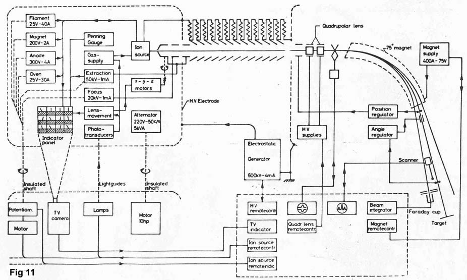
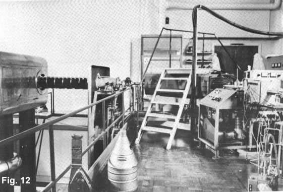 Fig. 12. The 600 keV accelerator
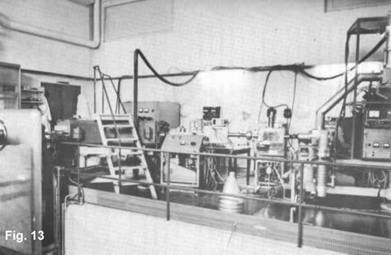 Fig. 13. Target arrangement
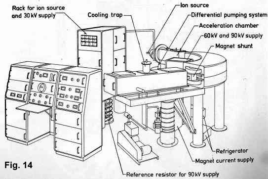 years it has to an increasing extent been used for ion implantation and other, solid state state physics applications. A more detailed description of the isotope separator is being prepared for publication and therefore, only the more important features will be mentioned here.
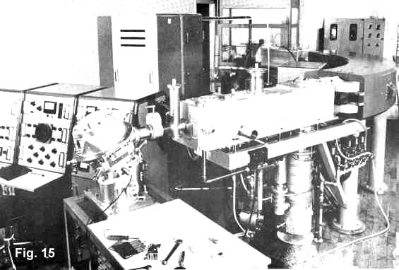 the beam direction for ?M/M = 1/100. The exit of the magnet is curved in such a way that the focal line is perpendicular to the central beam direction. The mass number range for beams passing simultaneously through the magnet is ?M/M = 0.06. Under favourable conditions, the enhancement is approx. 5000. The maximum beam current is given by I ~ 5000/M½ uA